[diagram] electrical power diagrams Tapetech® loading pump schematic (76tt) Hydraulic gear pump diagram
Experiment #10: Pumps – Applied Fluid Mechanics Lab Manual
Ideal logic overrun pump diynot Pump system centrifugal pressure flow fluid rate tutorial figure pumpfundamentals Centrifugal diffuser vaned impeller parts
Refrigeration: refrigeration pump down cycle
1. main components of a centrifugal pump (taken from [47])Wiring drayton plan pump overrun diynot diy badri mar Pump centrifugal schematic pumps experiment impeller inlet typical mechanics shaft characteristic casing discharge libretextsSolved: chapter 6 problem 107p solution.
Pump suction and discharge piping diagramPumps pump plan diynot Schematic diagram of the centrifugal pump with a vaned-diffuser. the[diagram] shallow well pump installation diagram.

Single line diagram of power plant
[diagram] wiring a water pump diagramHow to design a pump system Types of automatic pumpdown control systemsHouse takes ages to heat up.
Pump on timer with switch overrideWiring of flotec well pump diagram : submersible well pump wiring Lab manualMech4study: centrifugal pump: principle, parts, working, types.

Wiring diagram of a single phase water pump
Pump down refrigeration diagram wiring system cycle controls refrigerationbasics refrigerant explained compressor gif liquid pressure lowS plan pump overrun wiring help required Refrigeration automatic control types cycles diagram defrost system thermostat systems electric different airMech4study: centrifugal pump: principle, parts, working, types.
Down pump procedure zoneS plan with 2 pumps 1 pump 24/7 Wiring flotec submersible lovetoknowIdeal logic pump overrun.

[diagram] three phase to single phase diagram
"rational preparedness" : the blog: our experience with the simple pump5. schematic diagram of a simple pump-pipe system Water pump schematicFig-2-pump-down.
Refrigeration pump down schematicFirst pumpdown with the new setup. : r/hvac Pump down fig refrigeration say air quality defrost doExperiment #10: pumps – applied fluid mechanics lab manual.

Pump tapetech schematic loading schematics
Pump experienceHydronic primary secondary piping diagrams Pump-down procedure.... — heating help: the wallPump down system.
.

Solved: Chapter 6 Problem 107P Solution | Fundamentals Of Engineering
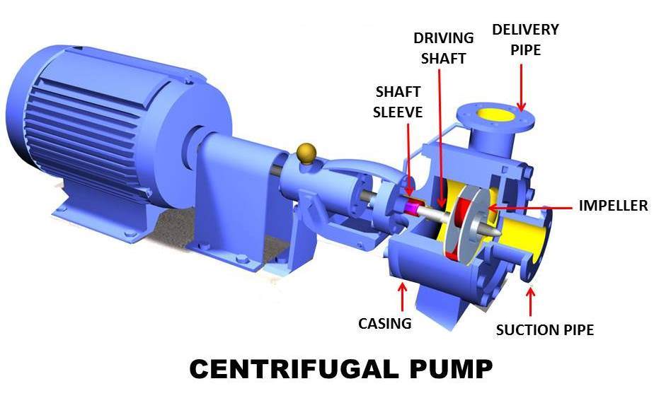
mech4study: Centrifugal Pump: Principle, Parts, Working, Types

S Plan with 2 Pumps 1 Pump 24/7 | Page 3 | DIYnot Forums
![[DIAGRAM] Wiring A Water Pump Diagram - MYDIAGRAM.ONLINE](https://i2.wp.com/az417944.vo.msecnd.net/diagrams/manufacturer/kohler/kohler-portables/wp-2-0/wp20-3001-2-inch-pro-water-pump/water-pump/diagram.gif)
[DIAGRAM] Wiring A Water Pump Diagram - MYDIAGRAM.ONLINE
![[DIAGRAM] Three Phase To Single Phase Diagram - MYDIAGRAM.ONLINE](https://i2.wp.com/electrical-engineering-portal.com/wp-content/uploads/2017/10/three-phase-power-system-single-line-diagram.png)
[DIAGRAM] Three Phase To Single Phase Diagram - MYDIAGRAM.ONLINE

Pump down system

Experiment #10: Pumps – Applied Fluid Mechanics Lab Manual